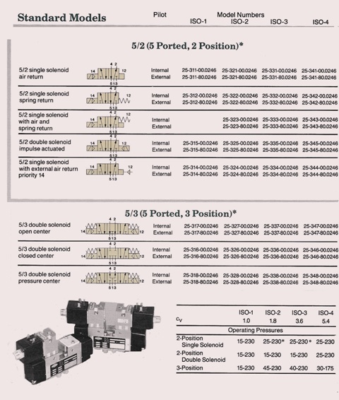
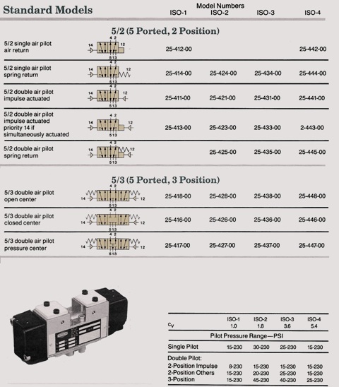
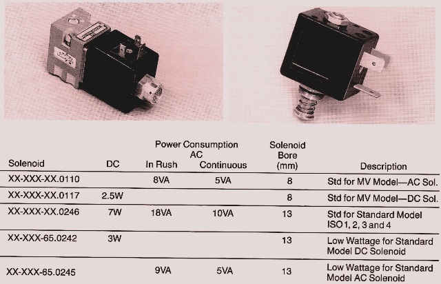
The top two charts show solenoids that don’t have connectors. Other charts will have the connectors on them. If you see an ISO beside next to it, it will show the internal solenoid pilot. Some of the specs for the chart at the bottom. The pilot solenoid valve that use filtered air can be lubricated or non lubricated. 230 PSI if for the pressure range vacuum. Also, if you model is external piloted, then you should at all times have the minimum pressure for the pilot supply.
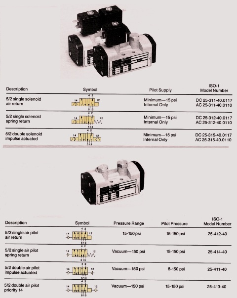
The flow can go in either direction. Vacuum pressure range .05″ of water to 230 psi. You can have this manually operated. Vales that are directional with filtered air come lubricated or without.
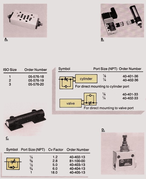
A. On your sub-plate you can go single or multi station on your manifold. The exhaust port have their own adjustment screw. Make sure to turn it CW to cut off flow and lower the exhaust port air flow to leisurely cylinder speed. B. Has condensed inline mounting. You can get this so you can do either air cylinder ports or valve ports. You can change the flow rate by rotating the valve barrel. C. If you have a standard model you can get it as a manual operation. You can get it as a whole valve. You will need to have the manual model number in order to get the correct part. D. Some of the aspects are it has a large flow rate, operating pressure can be adjusted to low, the regulating range is huge and has exact settings on the locking nut. On the introduced pressure regulator that goes between the valve and sub plate to set the inlet pressure that goes to the valve and to the manifold.
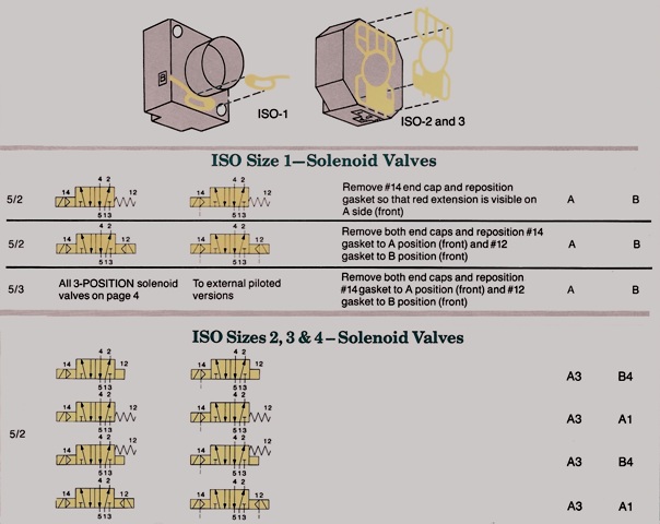
These are made in a way that the form of the end cap and extra placement of gaskets gives an apparent guide of the task of the unit when it is put together. The top chart shows ISO -1, gaskets are placed so A and B extensions can be seen on each side of the endcap. ISO -2, 3, 4 you have two placements of each end cap and you have four of the red gasket. A is marked on one side and B on the other one.
If you need more information on solenoid valves and manifolds, Call us at 662-871-8403 [email protected]