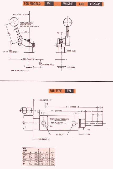
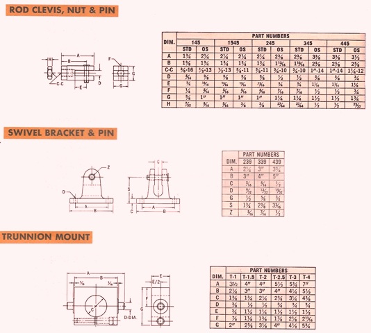
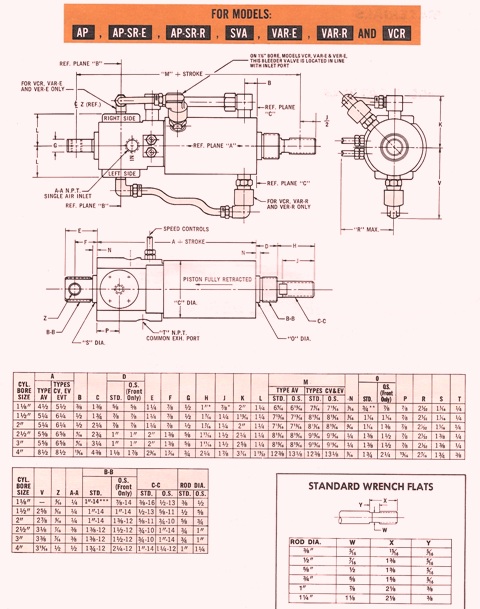
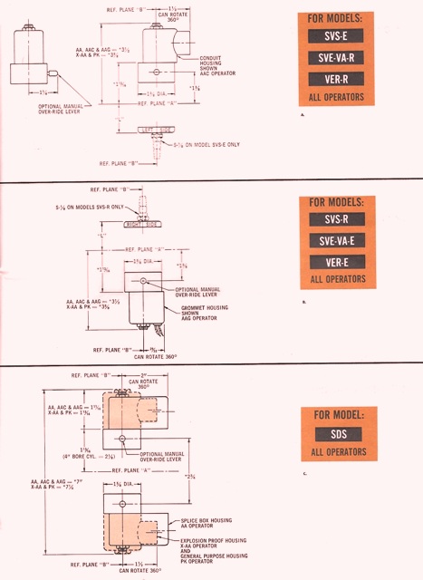
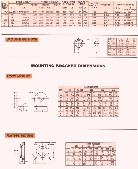
If you have unit NH SR-R the handle assy is on the left side. Rotate it in direction. You can situate the handle up to 180 degrees. Top chart.You can expect the trunnion mount not to tighten on all the way when you receive it in. You can do that when you do the final installing.* means models that are larger H = 1 3/8 and J = 1 1/4 ** means 7/8 on unit CV only *** means 1: thru 14 rear and 3/4- 16 front on units AV and EV 1″ thru 14 Rear 7/8 thru 14 front on units CV Disregard measurements E, F & N if your are laying out cylinder that has a tail section that is not there. Measurements A on a 4″ bore, if no tail it is 8″A. Match up A and B with some that are on the top outlook. If you have units AA, XAA, AAG & PK housing measurements look below. B. Match up A and B with some that are on the top outlook. If you have units AAC housing measurements look at AA, XAA & PK measurements below. C. Match up A and B with some that are on the top outlook. If you have units AAC & AAG housing measurements look above.First chart mounting brackets *means units CV regular cylinders have OS mount or a mounting nut for the front. ** means is made for the front head only. the back is A-214 Second Chart – Your mounting nuts are a given, they come with the falnge or foot mounts. They are also quoted in the price for mounts. You can buy themselves. Mounting Brackets – NT means you can put them on if you are using the front foot mount exclusively. Flange Mount – on the front flange mounting (NT) you can put that on. Rear flange mounting (J2) you can put this on and it will give you tail flush that has a flange mounting area.
If you have further questions, call us at 662-871-8403